What are Current Sense Resistors?
Current sense resistors, or shunt resistors, are devices used to gauge the flow of current. They detect and convert current to a measured output voltage. Current sense resistors are generally low-value, high-power resistors. They are designed for low resistance to minimise power consumption and to eliminate the risk of short circuits which are likely to damage other components.
The proportional relationship between voltage and current, according to Ohm’s Law enables a sensor circuit to measure the amperes delivered to a load in real-time. This is a cost-effective and straightforward method of current flow measurement and is used to mitigate the effects of short-circuits or overloads and to maximise the efficiency of electrical systems.
At TT Electronics, we offer a full spectrum of resistor technologies and a broad standard product range, in addition to providing custom engineering solutions. We dedicate ourselves to staying on top of the competitive landscape engineers are faced with today when designing a current flow measuring system.
In this article, we discuss the fundamentals of current sense resistors, resistor selection and usage, and its various applications in different industries with examples.

Don't have time to read the whole guide right now?
Let me send you a copy so you can read it when it's convenient for you. Just let me know where to send it (takes 5 seconds):

Chapters
Chapter 1
Current Sense Resistors: Cost-Effective Current Flow Measurement
Current sense resistors are generally positioned in-line on the conduction path between the power source and the load. The part is usually engineered for extremely low resistance values to minimise the voltage drop and the power loss. Typical resistance values for current sense resistors fall on the milliohms scale.
The underlying theory of current sense resistors follows the working principles of standard electrical resistors. However, while a standard resistor is primarily used to regulate current, a current sense resistor is used for monitoring purposes.
They are often connected to amplifiers to minimise the impact of noise while maintaining certain levels of resolution. Where the subsequent circuitry is at a different voltage from the current path, an isolation amplifier is used. This is not a mandatory configuration but choosing between isolated and non-isolated circuits is a crucial question to pose when designing a current flow measurement system.
Voltage drop is a critical metric when choosing a current sense resistor. Interposing the current sense resistor between the supply and the load will cause some measure of power dissipation due to the voltage drop as the current passes through the resistor. This constitutes wasted power that does not reach the load and is instead dissipated as heat, which can further impact the performance of the device.
Chapter 2
Four Common Current Sensing Methods
The first task for a designer with a current to measure is to select which of the four conventional current sensing methods to use.
These are listed below, with the advantages and disadvantages of each. Current sense resistors, with the benefits of low cost and accurate wideband measurement, are frequently the best answer.

[source]
Chapter 3
How to Choose and Use a Current Sense Resistor: Sizing and Selection
In many applications, it’s essential to measure the current being delivered to the load, which could, for example, be a heater, a motor, or a circuit board. There are many issues associated with this fundamental challenge. Some include whether to use an isolated or non-isolated sensor, use high-side or low-side sensing, and providing the analogue front end for the sensor (such as isolated/non-isolated, maximum common-mode voltage, and more).
For a combination of performance, simplicity, and cost reasons, high-side current sensing using a discrete sense resistor is among the most common approaches used. The resistor is placed between the supply rail and the load, and the voltage across the resistor is measured. By the basic application of Ohm’s Law, I = V/R, so the current is easily determined.
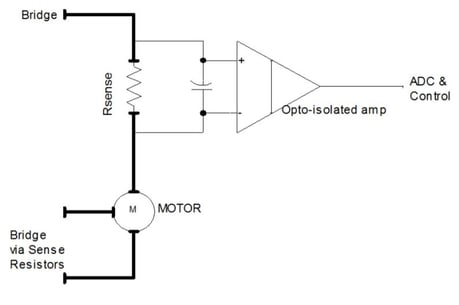
The high-side sense resistor is often used to measure current to a load via the IR drop across it; it is shown here with an isolation amplifier between the resistor and the front end and A/D converter.
The first and most obvious question is,
"What is the right value of the sense resistor?" It’s here that a simple engineering question reveals the trade-off dilemma.
On one side, you’d like this resistor to be large enough, so the voltage across it reaches several volts. This improves the accuracy of the reading by boosting signal-to-noise ratio (SNR), minimises the impact of noise, and maintains meaningful resolution at the lower end of the range.
But the voltage across the resistor also has several downsides. It subtracts from the voltage which is delivered to the load, and its presence can upset any closed-loop control since the real load is now in series with this interposed element.
Further, it dissipates power by basic I2R calculation. This last factor has two aspects:
- It represents wasted power not going to the load, thus decreasing system efficiency.
- It is heat which must be dissipated and can impact reliability.
A quick calculation clarifies the problem. Assume a modest 10A maximum current and a 0.5Ω resistor. The maximum voltage across the resistor will be 5V, which is undoubtedly good value for accurate measurement. Still, there is the loss of 5V of the supply rail headroom, and heat dissipation of 50W, are likely to be significant concerns.
This trade-off resolves that most medium-to-higher current designs keep the resistor small, on the order of a few milliohms and less, such as the TT Electronics LRMA Series with a range of 0.5mΩ to 300mΩ.
However, this means that the resistor interface must capture relatively small voltages and changes in them, calling for careful layout design and good SNR. Adding to the challenge is that the resistor power rating must be sized for the dissipation, which can easily reach many watts since dissipation is proportional to the square of the current.
For this reason, milliohm current-sense resistors are available with power ratings from fractions of a watt to tens of watts and more. For example, the LRMAP3920 series of low-resistance metal-alloy power resistors offer standard power ratings up to 5W and thermal substrate power ratings up to 10W, with resistance values from 0.2mΩ to 3mΩ.

Despite the small 5.2 mm × 10 mm footprint of the LRMAP3920 series of low-resistance metal-alloy power resistors, they can dissipate up to 5 W and have a thermal substrate power rating up to 10 W.
The resistor must be sited in a location where it will have adequate cooling, and a heat sinking with generous copper areas may be needed. Being mostly composed of welded metal elements, the temperature at which such a resistor can operate is only restricted by the need to prevent the solder joints from approaching a melting point. Typically, element temperatures up to 170°C are supported, making these suitable for underhood automotive use.
For current sense resistors, PCB layout is critical to achieving an accurate result. Even for two-terminal resistors, the connection traces should be four-wire Kelvin configured. Including copper trace in the sensed current path must be avoided; even if the resistance error can be calibrated out, it will introduce unnecessary temperature sensitivity to the circuit.
Takeaway: deciding on a specific value, style, and installation of even a component whose performance can be fully understood by two basic equations – namely, V= IR and P = I2R – involves trade-offs, constraints, and competing priorities.
What is Kelvin Configuration?
A Kelvin configuration resistor features four leads or terminations. Four-terminal sensing is also known as "Kelvin sensing, after William Thomson, Lord Kelvin, who invented the Kelvin bridge in 1861 to measure very low resistances using four-terminal sensing." [source]
These four-terminal resistors enable current to be applied through two opposite leads and a sensing voltage to be measured across the other two leads. The Kelvin configuration effectively eliminates the resistance and temperature coefficient of the leads.
Chapter 4
Designing Tips with Current Sense Resistors to Measure Current Accurately
1. Choosing the Best Ohmic Value
Selecting the best ohmic value is a question of balance. If it is too high, then power will be wasted, excess heat generated, and voltage regulation lost. If it is too low, then the sense voltage will be correspondingly low, so issues of noise and resolution will limit accurate measurement.
2. Picking the Right Power Rating
Power rating is sometimes a function of the PCB layout design as well as of component selection.
3. Selecting the Resistor Technology
Different applications require different resistor technologies. Many current sense resistors are in the category of bulk metal technology. This means that the element is a self-supporting piece of resistance metal alloy.
4. Optimising the PCB Design
PCB track design around current sense resistors is generally more critical to performance than for normal resistors.
5. Managing Heat
Whether your design requires the resistor to dissipate power at a significant proportion of its rating or to have a minimal temperature rise to minimize TCR errors, it’s essential to understand how the heat will be removed and where it will go.
6. Allowing for Current Surges
Often a design must accommodate high surges in the current above the maximum current which needs to be accurately measured.
7. Derating for High Temperature
As with any resistor, if the ambient temperature is higher than the rated temperature, power derating must be applied.
8. Understanding Thermal EMF
When using a metallic element shunt with high heat dissipation and low sense voltage, consideration may need to be given to thermoelectric voltages.
9. Reducing Inductive Errors
The combination of a high current path and a low signal voltage makes current sense resistor circuits particularly vulnerable to inductive errors.
10. Combining Multiple Resistors
Designers are sometimes forced to use more than one current sense resistor connected in parallel, either to meet a high power or surge rating or to achieve an ohmic value lower than the minimum available.
Full article: 10 Tips for Designing with Current Sense Resistors
Conclusion
Measuring current flow is essential for managing system performance.
TT Electronics is one of the world’s leading suppliers of precision electrical components.
We have supplied cost-effective, RoHS compliant current sense resistors for an extensive range of applications, furnishing engineers in a variety of electronics sectors with practical solutions for current flow measurement.